Description
Description and Technical Specifications :
Tatsam’s Fire Alarm and detection systems help to proactively identify fire incidents. The goal is to catch the fire at an early stage and raise an alert (via visual or audio) to enable safe evacuation of the area.
Tatsam’s fire alarm is a unit made of several devices, which uses visual and audio signalization to warn people about a possible fire, smoke, or carbon monoxide occurrence in the area of coverage. Fire alarms are usually set in fire alarm systems to provide zonal coverage for residences and commercial buildings. The warning signal is either a loud siren/bell or a flashing light, or it can include both. Some fire alarm systems use additional warnings, such as sending a voice message or making a phone call.
How a Fire Alarm System Works :
Tatsam’s fire alarm systems use automatic functions to detect the occurrence of an event that may result in a fire. They receive a signal from a fire sensor (smoke, heat or carbon monoxide detector) and automatically transmit it to the fire alarm panel.
The fire alarm panel activates the flashers or the sounders, turns on sprinklers (or they can be activated along with the detector), or makes a call to the authorities or to the occupants. If the fire alarm system is addressable, the source of the occurrence will be pointed on the control panel. Users on separate floors or in connected buildings can be notified in several ways: by horns, gongs and loudspeaker messages advising appropriate action for each department.
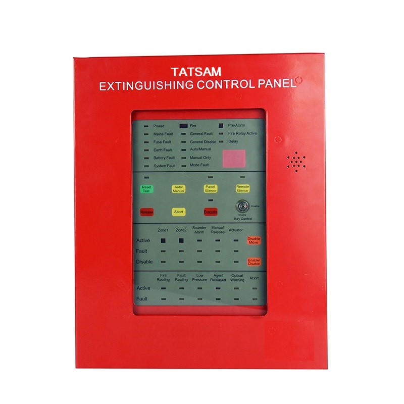
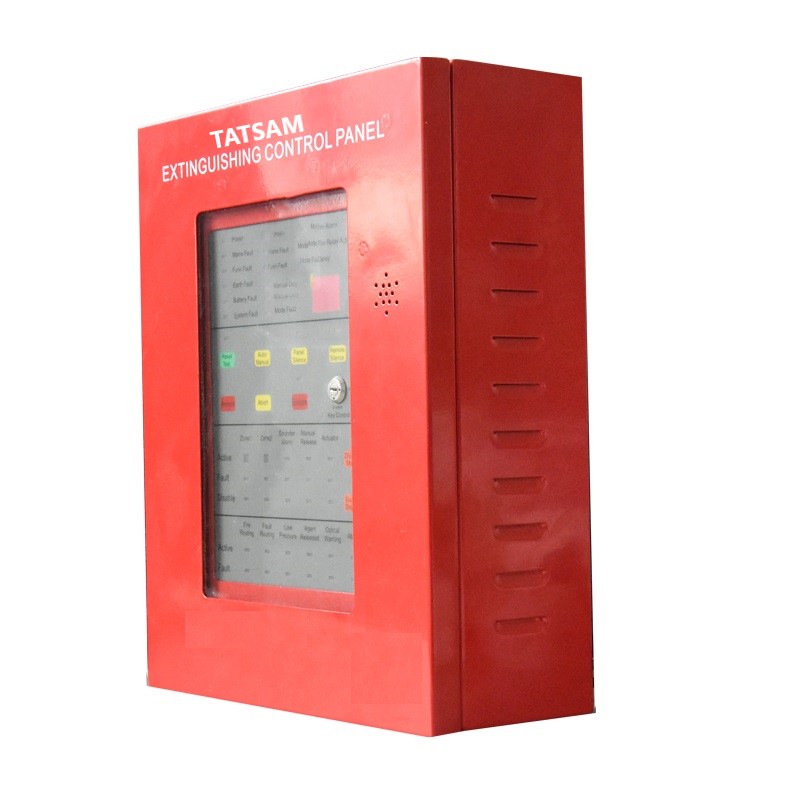
Tatsam’s AW-GEC21 extinguishing control panel is designed in compliance with the requirements of European standards of EN54-2, EN54-4 and EN12094-1. This panel can be used in FM200, CO2, IG541, Novec1230 and other gas fire extinguishing systems.
| Parameters | |
| AC input: | 220VAC 50Hz |
| DC output from power board: | 24VDC (19V-28V) and 5VDC (4.9V-5.1V) |
| Voltage for MCU: | 5V for power board MCU, 3.3V for other MCU |
| Current at 24VDC from PSE: | <450mA standby current |
| Maximum current from PSE: | 1.4A (except batteries charge current) |
| Batteries discharge current: | 1.85A maximum, current-limited |
| Auxiliary power output: | 24VDC, 200 mA max, current limited |
| Batteries: | Two 12V/ 2.3AH maintenance-free lead-acid batteries series connection |
| Zone alarm current: | 6-27mA |
| Detector numbers in each zone: | 16 pcs |
| Alarm terminal maximum output current: | 200mA maximum |
| Temperature range: | 15 to 40°C (23~104°F) |
| Humidity: | 5 to 95% RH, non-condensing |
| The wire between interface board (Panel) and detector (recommended): | 2-core shielded cable for 12 to18 AWG (0.75 to 2.5 mm2) |
| Panel dimension: | (L)350*(W)280*(T)112.5mm approx. |
Installation
- The panel shall be mounted on a dry, flat wall, maintained at sight height to ensure external chassis balance. The panel should be fixed by 3 pcs of M6 screws properly.
- The panel should not be installed in a sealed environment or near an over heat source. Suitable insulated cables should be used in the corresponding position. If additional cable entry points are required, all chips and debris generated by drilling must be removed before the panel is energized.
- Preparation: ensure that the installation site is free of construction dust, debris, extreme temperature ranges and humidity.
- The ground wire shall connect to the AC power supply. We recommend using 16AWG (1.3mm2) wire to wiring.
- Make sure the AC circuit breaker is disconnect before wiring from the AC circuit (220-240 VAC) to the power terminal.







Reviews
There are no reviews yet.